Desmo
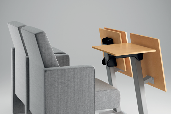
Desmo is an independent and versatile table with a metal supporting structure, distinguished by its strong aesthetic impact. The writing surface is foldable, allowing for quick and efficient closure.
The V9’s clean lines and narrow profile makes for a functional and comfortable viewing experience for any auditorium, stadium, or theater. Ergonomically designed for maximum comfort and minimal space.
[popup_trigger id=”1101″ tag=”span”]View Specs[/popup_trigger]
Desmo is an independent and versatile table with a metal supporting structure, distinguished by its strong aesthetic impact. The writing surface is foldable, allowing for quick and efficient closure.
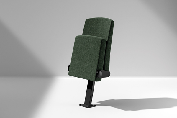
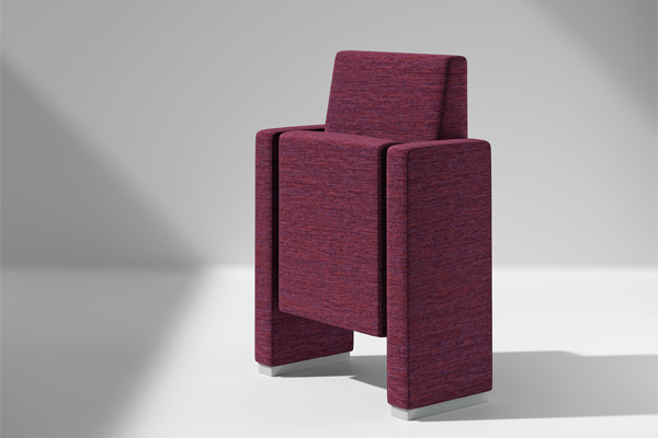
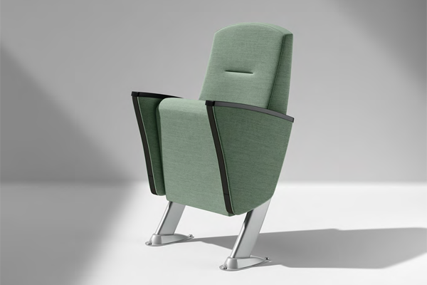
Cassiano is a compact, streamlined armchair mounted on a central base. Its individual floor-mounting system and integrated armrests make it ideal for installation in tight curves.The foldable version is specifically engineered for use with mobile tribune technology.
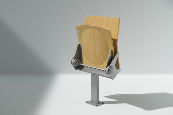
Olimpico is a compact, rational armchair on a central foot. The individual floor-mounting system and integrated armrest make it ideal for installation in narrow curves. The folding version is specifically designed for “Mobile tribunes” technology.
The V Chair by Navetta Design combines timeless elegance with robust durability, making it an ideal choice for high-traffic environments like auditoriums. Built from steel and wood, the V Chair is designed to withstand the rigors of everyday use while maintaining a classic aesthetic.
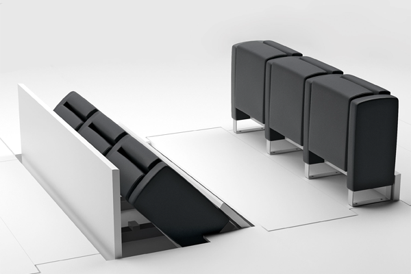
The In-floor seating system represents a groundbreaking advancement in theater design, seamlessly combining elegance with innovation. This system allows the auditorium chairs to rise gracefully from the floor at the touch of a button, allowing the theater to adapt quickly to different event formats and seating needs.
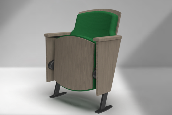
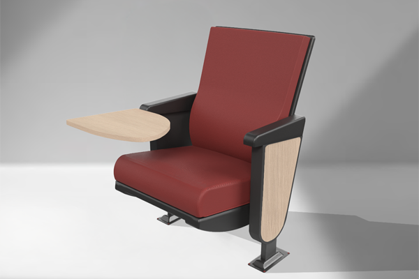
Metropolitan is a complete collection featuring a highly varied range of sides and backrests, all perfectly coordinated and interchangeable. This makes it ideal for classic or contemporary settings. The Rossini sides feature armrests carved from a single piece of solid wood, with soft and elegant lines.
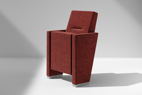
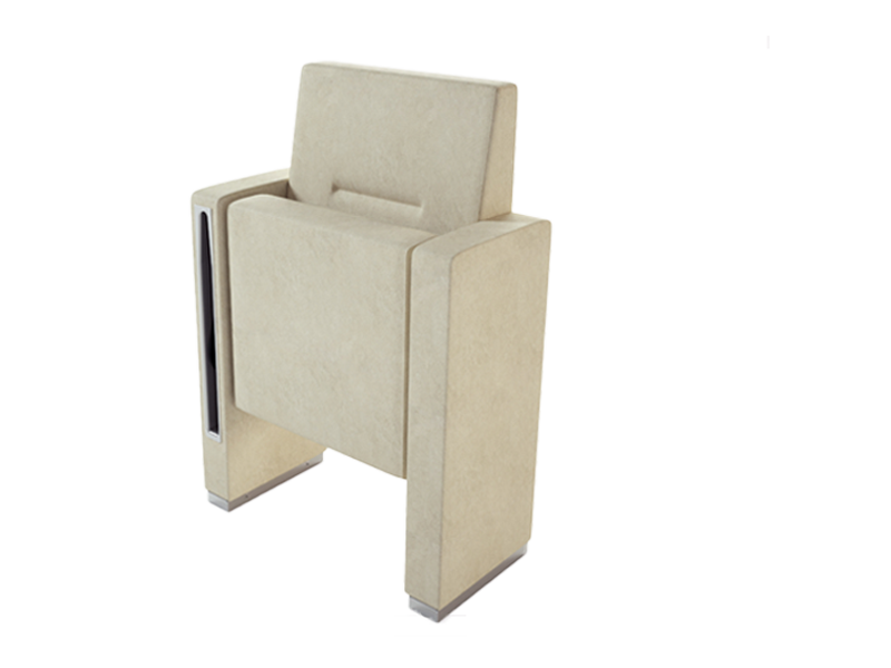
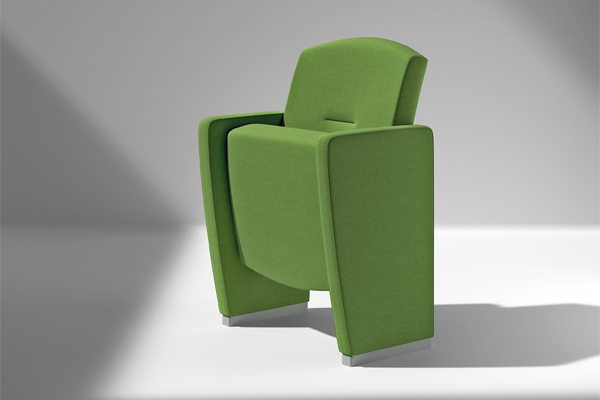
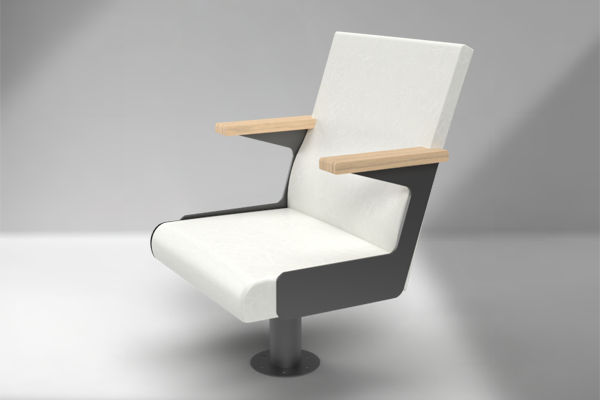
Each element of Time exists along a single elegant plane. Its well-defined shapes and angles make it unique and immediately recognizable. The tapered sides determine the placement and volume of the other elements, which follow their lead. This architectural rhythm is particularly pronounced when rows of these chairs are placed side by side.
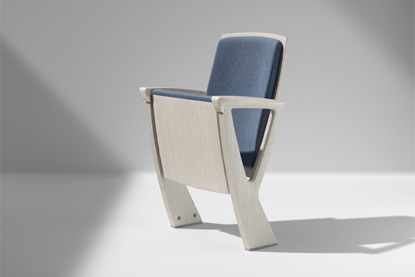
This shape makes for an ergonomic recline and an eye-catching silhouette perfect for auditoriums, theaters, and music venues.
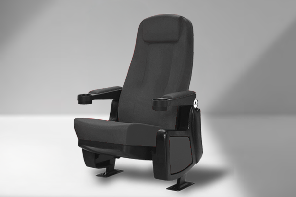
Functionally designed with ergonomics in mind, the Capri chair contours to the viewers body and makes for a long-lasting comfortable experience.
The V9's clean lines and narrow profile makes for a functional and comfortable viewing experience for any auditorium, stadium, or theater. Ergonomically designed for maximum comfort and minimal space.
The Contina Seating System provides elegant, comfortable, and reliable seating at an affordable price–perfect for auditoriums and other larger venues.
Characterized by its great versatility and innovative design, Eidos includes a wide range of models.
The Jury is a simple and classic solution for fixed chair environments. Made with dependable materials, a durable steel frame and wood arms the Jury is sure to withstand the trials of the courtroom.