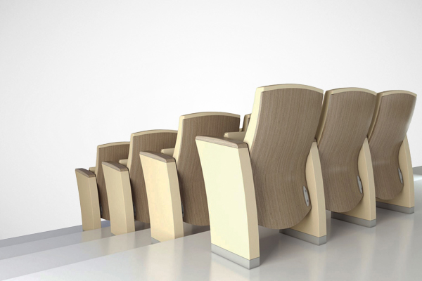
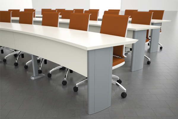
Navetta designs and manufactures premier lecture room and auditorium furniture with a focus on striking aesthetics, meticulous engineering and unparalleled value. Navetta’s revolutionary products for lecture halls, seminar rooms, and auditorium furniture have created beautiful and productive environments for colleges, universities, hospitals, and other institutions.
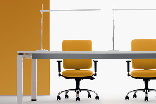
Navetta’s history spans 40 years of successful seating solutions and innovations. Navetta provides custom and functional learning environments by understanding your needs, and providing beautiful and well-designed spaces that exceed your expectations. Let us help you create your space!
PART 1 – GENERAL
1.1 RELATED DOCUMENTS
A. Drawings and general provisions of the Contract, including General and Supplementary Conditions, apply
to this section
1.2 SUMMARY
A. This section includes the following:
1. Common standard floor mounted chairs as detailed in Part 2 of these specifications.
1.3 SUBMITTALS
A. Product data for each type of product specified. Include installation methods.
B. Shop drawings, prepared for architectural drawings and from field dimensions, showing the seating layout,
seat numbering sequence, chair sizes, and aisle widths. Also show a section view with profile dimensions
of the seating and back-to-back dimensions.
C. Samples for initial selection purposes in the form of manufacturer’s color charts or samples of materials
showing the full range of standard colors, finishes, and patterns.
1. Fabric
2. Metal Finishes
3. Wood Finishes
D. Statement signed by the theater seating manufacturer confirming that the products submitted comply with
the specified requirements.
1.4 QUALITY ASSURANCE
A. Provide installer’s qualifications confirming the installer is qualified to install the manufacturer’s chairs
B. Provide seating that complies with California Technical Bulletin 117.
C. Obtain each type of seating, including accessories and mounting components, from a single manufacturer.
D. Design and install seating with end standards aligning from first to last row and with backs and seats varied
in width to optimize sightlines. Comply with ADA rules and regulations.
1.5 PROJECT CONDITIONS
A. Environmental Conditions: Do not install seating until space is enclosed and weatherproof, wet work in
space is complete and dry, installation of finishes including painting is complete, and ceilings are complete.
Do not install seating until ambient temperature and humidity conditions are continuously maintained at
final occupancy values.
1.6 DELIVERY, STORAGE, AND HANDLING
A. Deliver seating in manufacturer’s unopened cartons clearly labeled with manufacturer’s name and
contents.
B. Handle seating in manner to prevent damage.
1.7 EXTRA MATERIALS
A. Furnish from the same production run as the materials installed. Package materials with protective
covering and identify with labels describing contents.
1. Seat and back covers to be furnished in a quantity equal to 5 percent of the amount of chairs
installed.
PART 2 – PRODUCTS
2.1 SEATING
A. Provide from Navetta division of Shuttlesystem LLC, corporate headquarters 7697 Innovation Way,
Suite 400 Mason, OH 45040, manufacturing plant 1330 Potts Ave, High Point, NC 27260, the Teatro
“A1” model as follows:
1. Basic floor mounted chair.
2. Inner upholstered seat and back.
Teatro A1 Specifications – Theatre Seating
Page 2 of 5
3. Outer wood veneer seat and back with stained edges.
4. Wood armrests.
5. Aisle lights where indicated on the drawings.
6. Wood veneer end panels where indicated on the drawings.
B. Model noted is based on the Navetta. Teatro “A1” model with the intent of establishing the high level of
quality required for the project. Other brands submitted for approval will be given consideration provided
that a full seating mock-up, along with a complete list of specification discrepancies between the proposed
substitution and the product specified is received at least 10 working days prior to the bid date.
1. By offering a quote for this project, the bidder assumes full responsibility for complying with the
specifications for this project and shall be totally responsible for any expenses incurred if the
product quoted does not comply with the specifications.
C. Failure to comply with the warranty described in Part 4 of these specifications will be cause for
disqualification.
2.2 MATERIALS
A. Padding material shall be high resiliency polyurethane foam which conforms to the standards of the
California Bureau of Home Furnishings 117-75. The back shall be 1-3/4” thick. The seat shall be 3” thick.
B. Seating fabric shall be manufactures standard colors unless selected by architect or customer the
color to be selected from the standard choice of colors. All upholstery shall be first quality without
creases, stretch lines, or wrinkles.
C. Exposed wood on the outer back panel shall be veneer. The panel edges shall be stained to match the
veneer faces. The arms shall be solid wood. All wood shall be stained to match the architect’s sample.
2.3 FABRICATION, GENERAL
A. Fabricate the theater seating in contoured form for maximum comfort using materials that are carefully
selected to be free from defects, objectionable projections, or irregularities. Smooth round corners and
edges to present the least possible snagging and pinching hazards.
2.4 MOUNTING
A. Fabricate seating units for floor attachment, using standards that have been manufactured to conform to
the slope of the floor while maintaining seat and back in same angular relationship to standards throughout.
2.5 METAL STANDARDS
A. Frame shall be 3/4” x 2” x 16 gauge cold-rolled welded steel tubing, and 5/16” x 3” hot-rolled steel plate,
and 11 gauge formed steel brackets welded into one integral freestanding structure upon which the seat,
back, and arms are assembled. Pivot and stop pins shall be machined from cold-finished steel to
tolerances of +0.000 -0.005. Floor mount plate shall be 5/16” thick hot-rolled pickled-in-oil steel plate with
two countersunk holes for 1/4-20 mounting screws.
2.6 UPHOLSTERED CHAIRS
A. General: Fabricate theater seating with padding and fabric covering. Equip each seat with a gravity selfrising
mechanism so that unoccupied seats return to an upright position perpendicular to the base line of
floor of auditorium. Spring compensating mechanism will not be acceptable. Chair profile with the seat in
the upright position and without a tablet arm, cannot exceed 18”. The chair profile with the seat in the
upright position and with a tablet arm, cannot exceed 24”.
B. Seat Construction: Solid seat bottom construction comprised of a curved plywood veneer outer panel
fastened solidly and without voids to an inner structural plywood panel. The outer panel shall be 15mm
thick, faced one side with Grade A veneer centered across the width of the panel, and exposed plywood
laminations along the edges. The inner panel shall be 5/8” thick. Both shall be electronically glued
hardwood plywood and shall be fastened together with bayonet hanging brackets at the top and two steel
angles at the bottom, resulting in a rigid connection with no visible fasteners. The veneer face and edges
of the outer panel shall be stained to match the architect’s sample. The padding material shall be 3” thick
polyurethane foam, shall be glued to the inner panel, and shall conform to the California Bureau of Home
Furnishings Technical Bulletin 117. The complete seat assembly shall be supported by two 7 gauge
formed steel mounting brackets which will attach the seat assembly to the hinges on the standards. The
seat shall have a built-in counterweight to insure automatic self-rising without the aid of springs. Archspring
construction will not be acceptable.
Teatro A1 Specifications – Theatre Seating
Page 3 of 5
C. Back Construction: Solid back construction comprised of a curved plywood veneer outer panel fastened
solidly and without voids to an inner structural plywood panel. The outer panel shall be 15mm thick, faced
one side with Grade A veneer centered across the width of the panel, and exposed plywood laminations
along all edges. The inner panel shall be 3/8” thick. Both shall be electronically glued hardwood plywood
and shall be fastened together with bayonet hanging brackets at the top and two #8 x 3/4” trim head screws
at the bottom, resulting in a rigid connection with no visible fasteners on the outer wood panel. The veneer
face and edges of the outer panel shall be stained to match the architect’s sample. The padding material
shall be 1-3/4” thick polyurethane foam, 2-3/4” thick in the lumbar region, shall be glued to the inner panel,
and shall conform to the California Bureau of Home Furnishings Technical Bulletin 117. The complete
back assembly shall be supported by two 13 gauge formed steel brackets and two 3/8-16 hex head bolts
which will attach the back assembly to the frame.
D. Armrests: Shall be kiln-dried solid hardwood, nominally 1” thick x 2-1/2” wide x 12” long, stained to match
the outer seat and back panels. The armrest will be fastened to the steel frame arm support with one 10-
24 x 7/8” flat head machine screw and one 10-24 x 2-1/4” flat head machine screw into threaded inserts on
the underside of the armrest. Chairs equipped with tablet arms shall have armrests nominally 1” thick x 2-
1/2” wide x 18” long and shall be attached to the steel frame arm support with four #8 x 3/4” sheet metal
screws.
E. Hinge: The seat hinge shall be a weldment consisting of a 7 gauge hot-rolled pickled-in-oil steel component
and shall be formed and punched to receive a 0.56” id x 0.75” od x 0.5” long steel bushing. A selflubricating
nylon sleeve shall be fitted between the seat hinge and the standard seat hinge pin. The hinge
shall be machined to provide a positive stop location for the seat in both occupied and unoccupied
positions. The hinge shall be fitted with a plastic cover to eliminate all pinch points and shall include a
3/16” thick urethane rubber pad to dampen noise upon the seat return to the vertical position.
PART 3 – OPTIONS
3.1 END PANEL
A. Provide manufacturer’s standard end panel at the end of the row. The configuration of the panel shall
follow the angle of the frame and back at the rear, and shall be vertical at the front end. The panel shall be
constructed of 3/4” thick plywood with veneer on both sides and 1/8” thick solid wood on the vertical edges.
The end panel shall be stained to match the outer wood seat, back, and armrests.
3.2 AISLE LIGHT
A. Aisle lights shall be provided in accordance to the locations shown on the architectural drawings. The units
shall be of low voltage (24v) type and the light tube shall fit into a routed area on the underside of the
armrest. The chair frame shall be prepared to accept the power wire. The necessary access holes and
blank cover plates shall be provided. The chair manufacturer shall also provide the necessary
transformers. All wiring and electrical connections shall be conducted at the job site and shall be the
responsibility of others.
3.3 HARDWOOD EDGES, OUTER SEAT AND BACK
A. Outer plywood panels shall be trimmed in 1/8” thick hardwood on the top and vertical edges. The
hardwood shall match the face veneer species and be stained to match.
3.4 INSET UPHOLSTERY, BACK
A. Back Upholstery shall be inset to expose the veneer face on the inside of the outer back panel. The veneer
on the inside face on the back panel shall match the veneer species on the outside face and be stained to
match.
3.5 SEAT AND ROW IDENTIFICATION TAGS
A. Provide manufacturer’s standard shape brass number and letter plates. Font shall be Times Roman. The
size of the font on the seat number plates shall be 27pt; the size of the font on the row letter plates shall be
42pt. The number plates shall fit into a recessed area at the top edge of the seat. The row letter plates
shall fit into a recessed area at the back of the armrest.
3.6 REMOVABLE CHAIR
A. Provide manufacturer’s standard one, two, or three chair removable units which shall include an integrated
steel sled-base that is engineered to conform to the row radii and includes two through holes per chair for
floor mounting.
3.7 FREESTANDING REMOVABLE CHAIR
Teatro A1 Specifications – Theatre Seating
Page 4 of 5
A. Provide manufacturer’s standard freestanding removable chair which shall include an integrated steel sledbase
that is engineered to conform to the row radii and includes extended length floor plates to allow the
chairs to remain stable with no physical attachment to the floor.
3.8 TABLET ARMS
A. Tablet arm shall be two-motion fold-away style, constructed of 1/2” medium density fiberboard, faced two
sides with matte black high-pressure laminate. The edges shall be finished with a vinyl T-molding trimmed
flush with both top and bottom surfaces.
3.9 POWER/DATA
A. Where indicated on the drawings, chair frames shall be equipped with a 115v/15amp power outlet and a
RJ-45 Category 6 data port located on the front of the armrest gusset. Wire raceways shall be provided for
routing of the wires from chair to chair. All wiring and electrical connections shall be conducted at the job
site and shall be the responsibility of others.
3.10 BOOKRACKS
A. The bookrack shall be constructed of hardwoods and hardwood plywood. Bookrack shall be assembled
with tongue and groove construction and finished with a catalyzed lacquer. The bookrack shall be attached
to the outer surface of the chair back. An optional attachment configuration shall consist of a steel
weldment attached to the chair leg. This configuration allows the bookrack to be located between chair
backs.
3.11 COMPLIANCE WITH CALIFORNIA TECHNICAL BULLETIN 133
PART 4 – WARRANTY
4.1 The theater seating manufacturer must provide a Lifetime Warranty to the original purchaser of the seating as
follows:
A. The seating manufacturer shall warrant it’s products against failures and manufacturing defects for the life
of the product. This warranty applies to the original purchaser and is non-transferable. The seating
manufacturer will provide parts and labor to replace defective parts for the first two years after the
installation. Thereafter, the manufacturer will provide replacement parts for the life of the product.
B. This warranty shall not cover damage from abuse, misuse, neglect, or act of God. Damage caused by
modifications to the product by anyone other than a Navetta authorized seating installation technician will
void this warranty. This warranty does not apply to fabrics or products not installed by Navetta authorized
seating installation technicians.
PART 5 – EXECUTION
5.1 EXAMINATION
A. Examine site conditions, with installer present, for compliance with requirements for construction tolerances
as they affect anchors and fasteners, and location of junction boxes.
B. Do not proceed until unsatisfactory conditions have been corrected.
5.2 GENERAL
A. Comply with seating manufacturer’s printed installation instructions applicable to products.
B. Locate seating in locations indicated on approved shop drawings, with required clearances.
C. Install standards in locations conforming to seating layout, with each standard attached to substrate by no
less than two anchoring devices of size and type required to insure that chairs are stable under conditions
of actual use.
D. Install chairs using manufacturer’s recommended hardware and fasteners. Insure that chairs in curved
rows are installed on proper radius and are oriented toward the center point of the radius. Verify that
moving components operate smoothly and quietly.
5.3 ADJUSTING
A. Adjust as required to assure that the seats in each row are aligned when in the upright position.
B. Touch-up minor abrasions and imperfections in painted finishes with coating that matches factory-applied
finish.
Teatro A1 Specifications – Theatre Seating
Page 5 of 5
C. Replace any upholstery that has been damaged during installation.
END OF SPECIFICATION
Download Teatro A1 Spec
Download Teatro C1 Spec
Download Teatro C3 Spec
PART 1 – GENERAL
1.1 RELATED DOCUMENTS
A. Drawings and general provisions of the Contract, including General and Supplementary Conditions, apply
to this section
1.2 SUMMARY
A. This section includes the following:
1. Common standard floor mounted chairs as detailed in Part 2 of these specifications.
1.3 SUBMITTALS
A. Product data for each type of product specified. Include installation methods.
B. Shop drawings, prepared for architectural drawings and from field dimensions, showing the seating layout,
seat numbering sequence, chair sizes, and aisle widths. Also show a section view with profile dimensions
of the seating and back-to-back dimensions.
C. Samples for initial selection purposes in the form of manufacturer’s color charts or samples of materials
showing the full range of standard colors, finishes, and patterns.
1. Fabric
2. Metal Finishes
3. Wood Finishes
4. Plastic Finishes
D. Statement signed by the theater seating manufacturer confirming that the products submitted complies with
the specified requirements.
1.4 QUALITY ASSURANCE
A. Provide installer’s qualifications confirming the installer is qualified to install the manufacturer’s chairs
B. Provide seating that complies with California Technical Bulletin 117.
C. Obtain each type of seating, including accessories and mounting components, from a single manufacturer.
D. Design and install seating with end standards aligning from first to last row and with backs and seats varied
in width to optimize sightlines. Comply with ADA rules and regulations.
1.5 PROJECT CONDITIONS
A. Environmental Conditions: Do not install seating until space is enclosed and weatherproof, wet work in
space is complete and dry, installation of finishes including painting is complete, and ceilings are complete.
Do not install seating until ambient temperature and humidity conditions are continuously maintained at
final occupancy values.
1.6 DELIVERY, STORAGE, AND HANDLING
A. Deliver seating in manufacturer’s unopened cartons clearly labeled with manufacturer’s name and
contents.
B. Handle seating in a manner to prevent damage.
1.7 EXTRA MATERIALS
A. Furnish from the same production run as the materials installed. Package materials with protective
covering and identify with labels describing contents.
1. Seat and back covers to be furnished in a quantity equal to 5 percent of the amount of chairs
installed.
PART 2 – PRODUCTS
2.1 SEATING
A. Provide from Navetta division of Shuttlesystem LLC, corporate headquarters 7697 Innovation Way, Suite
400 Mason, OH 45040, manufacturing plant 1330 Potts Ave, High Point, NC 27260, the Lyric “D1” model
as follows:
1. Basic floor mounted chair
Lyric D1 Specifications – Theatre Seating
Page 2 of 2
2. Inner upholstered seat and back
3. Outer wood veneer back with stained edges
4. Outer injection-molded plastic seat cover
5. Blow-molded plastic armrests
6. Aisle lights where indicated on the drawings
7. End panels where indicated on the drawings
B. Model noted is based on the Navetta Lyric “D1” model with the intent of establishing the high level of quality
required for the project. Other brands submitted for approval will be given consideration provided that a full
seating mock-up, along with a complete list of specification discrepancies between the proposed
substitution and the product specified is received at least 10 working days prior to the bid date.
1. By offering a quote for this project, the bidder assumes full responsibility for complying with the
specifications for this project and shall be totally responsible for any expenses incurred if the
product quoted does not comply with the specifications.
C. Failure to comply with the warranty described in Part 4 of these specifications will be cause for
disqualification.
2.2 MATERIALS
A. Padding material shall be high resiliency polyurethane foam which conforms to the standards of the
California Bureau of Home Furnishings 117-75. The back shall be 1 1/4” thick. The seat shall be 1 3/4”
thick.
B. Seating fabric shall manufactures standard colors unless selected by architect or customer the color to
be selected from the standard choice of colors. All upholstery shall be first quality without creases,
stretch lines, or wrinkles.
C. Exposed wood on the outer back panel shall be veneer. The panel edges shall be stained to match the
veneer faces. All wood shall be stained to match the architect’s sample. The outer plastic cover shall be
impact resistant polypropylene. The arms shall be high density polyethylene.
2.3 FABRICATION, GENERAL
A. Fabricate the theater seating in contoured form for maximum comfort using materials that are carefully
selected to be free from defects, objectionable projections, or irregularities. Insure smooth round corners
and edges to present the least possible snagging and pinching hazards.
2.4 MOUNTING
A. Fabricate seating units for floor attachment, using standards that have been manufactured to conform to
the slope of the floor while maintaining seat and back in same angular relationship to standards throughout.
2.5 METAL STANDARDS
A. Frame shall be 3/4” x 2” x 16 gauge cold-rolled welded steel tubing; 1/4” x 3 1/2” hot-rolled steel plate, 1/4”
x 2 1/8” hot-rolled steel plate and 11 gauge formed steel brackets welded into one integral freestanding
structure upon which the seat, back, and arms are assembled. Pivot and stop pins shall be machined from
cold-finished steel to tolerances of +0.000 -0.005. Floor mount plate shall be .100” thick hot-rolled pickledin-
oil steel formed and embossed for 1/4” mounting anchors. A molded plastic cap shall be fitted into the
embossed mounting area to conceal the anchoring hardware. Exposed floor anchoring hardware will not
be acceptable.
2.6 UPHOLSTERED CHAIRS
A. General: Fabricate theater seating with padding, fabric covering and injection-molded seat cover. Equip
each seat with a gravity self-rising mechanism so that unoccupied seats return to an upright position
perpendicular to the base line of floor of auditorium. Spring compensating mechanism will not be
acceptable. Chair profile with the seat in the upright position and without a tablet arm, cannot exceed 18”.
Lyric D1 Specifications – Theatre Seating
Page 3 of 3
B. Seat Construction: Seat construction is comprised of an injection-molded polypropylene cover fastened
securely to an inner upholstered structural steel frame assembly. The outer seat cover shall have a
textured exterior surface and internal molded reinforcing ribs for a solid warp-free construction. The inner
seat frame assembly shall consist of a 7/8” dia. X 16 gauge steel tube formed with a waterfall front edge
and welded into a rigid assembly with (2) 11 gauge X 1” steel brackets and (1) 1/4” diameter steel rod. The
seat frame shall be fitted with a cast iron counterweight to insure automatic self-rising without the aid of
springs. A series of (7) 2” wide elastic suspension straps shall be stretched and woven in place and
fastened to the steel seat frame with 1/8” dia. steel hooks. Arch-spring and/or S-spring construction will not
be acceptable. A layer of 1 3/4” thick molded polyurethane foam shall be applied over the elastic webbing.
Foam shall be fire retardant and conform to the California Bureau of Home Furnishings Technical Bulletin
117. The upholstery cover shall be sewn and fitted to the seat assembly with collapsible assembly rings
and nylon tension cord.
The outer injection-molded seat cover and upholstered inner seat assembly shall be joined together with
cast aluminum mounting brackets. Seat widths of 19” and 21” shall be fitted with narrow style mounting
brackets. Seat widths of 20” and 22” shall be fitted with width-extending mounting brackets. The complete
seat assembly shall be assembled to the seat hinges using (2) special purpose M10 Hinge Bolts and (2)
special purpose M10 Hinge Pins which are specifically designed to accommodate installation tolerances.
C. Back Construction: Back construction is comprised of a curved plywood veneer outer panel fastened solidly
and without voids to an inner structural plywood panel. The outer panel shall be 15mm thick, faced one
side with Grade A veneer centered across the width of the panel, and exposed plywood laminations along
all edges. The inner panel shall be 3/8” thick. Both shall be electronically glued hardwood plywood and
shall be fastened together with bayonet hanging brackets at the top and two #8 x 3/4” trim head screws at
the bottom, resulting in a rigid connection with no visible fasteners on the outer wood panel. The veneer
face and edges of the outer panel shall be stained to match the architect’s sample. The padding material
shall be 1-3/4” thick polyurethane foam (2-3/4” thick in the lumbar region), shall be glued to the inner panel
and shall conform to the California Bureau of Home Furnishings Technical Bulletin 117. The complete
back assembly shall be supported by two 13 gauge formed steel brackets and two 3/8-16 hex-head bolts
and shall be attached to the frame with (2) 1/4-20 machine screws.
D. Armrests: Shall be blow-molded of high density polyethylene and curved to match the leg mounting plate.
The armrest shall be fastened to the steel frame arm support with three #8 sheet metal screws.
E. Hinge: Shall be injection-molded of DuPont™ Zytel® 801 nylon. The hinge shall be molded with
provisions to provide positive stop locations for the seat in both occupied and unoccupied positions. The
hinge shall be fitted with a plastic cover to eliminate all pinch points and shall include (2) 7/16” thick
urethane rubber pads to dampen noise upon the seat stop in both the vertical and horizontal positions.
Note: Dupont™ and Zytel ®are registered trademarks of E.I.du Pont de Nemours and Co. or its affiliates
PART 3 – OPTIONS
3.1 VENEER END PANEL
A. Provide manufacturer’s standard end panel at the end of the row. The configuration of the panel shall
follow the angle of the frame and back at the rear, and shall be vertical at the front edge. The panel shall
be constructed of 3/4” thick plywood with veneer on both sides and 1/8” thick solid wood on the vertical
edges. The end panel shall be stained to match the outer wood seat, back, and armrests.
3.2 POWDER-COATED END PANEL
A. Provide manufacturer’s standard end panel at the end of the row. The configuration of the panel shall
follow the angle of the frame and back at the rear, and shall be vertical at the front edge. The panel shall
be constructed of 3/4” thick medium density fiberboard with a durable powder-coated black finish.
3.3 AISLE LIGHT
A. Aisle lights shall be provided in accordance to the locations shown on the architectural drawings. The
units shall be of low voltage (24v) type and the light tube shall fit into a recessed area on the underside of
the armrest. The chair frame shall be prepared to accept the power wire. The necessary access holes
and blank cover plates shall be provided. The chair manufacturer shall also provide the necessary
transformers. All wiring and electrical connections shall be conducted at the job site and shall be the
responsibility of others.
3.4 SEAT IDENTIFICATION TAGS
Lyric D1 Specifications – Theatre Seating
Page 4 of 4
A. Provide manufacturer’s standard shape polycarbonate number plates. Font shall be Times Roman. The
number plates shall fit into a recessed area at the top edge of the seat and shall be adhered with highstrength
pressure-sensitive tape.
3.5 ROW IDENTIFICATION AND DONOR TAGS
A. Provide manufacturer’s standard shape polycarbonate letter plates. Font shall be Times Roman.
3.6 REMOVABLE CHAIR
A. Provide the manufacturer’s standard one, two or three chair Removable units which shall include an
integrated steel sled-base that is engineered to conform to the row radii and includes two through holes
per chair for floor mounting.
3.7 FREESTANDING REMOVABLE CHAIR
A. Provide manufacturer’s standard freestanding removable chair which shall include an integrated steel
sled-base that is engineered to conform to the row radii and includes extended length floor plates to allow
the chairs to remain stable with no physical attachment to the floor.
3.8 BOOKRACK
A. The bookrack shall be constructed of hardwoods and hardwood plywood. Bookrack shall be assembled
with tongue and groove construction and finished with a catalyzed lacquer. The bookrack shall be
attached to the outer surface of the chair back. An optional attachment configuration shall consist of a
steel weldment attached to the chair leg. This configuration allows the bookrack to be located between
chair backs.
3.9 FLAT WOOD ARMREST
A. Shall be kiln-dried solid hardwood, nominally 1” thick x 2-1/2” wide x 12” long, stained to match the outer
back panel. The armrest will be fastened to the steel frame arm support with one 10-24 x 7/8” flat head
machine screw and one 10-24 x 2-1/4” flat head machine screw into threaded inserts on the underside of
the armrest.
3.10 CURVED WOOD ARMREST
A. Shall be kiln-dried solid hardwood, nominally 1 1/8” thick x 2 1/4” wide x 12 3/4“ long, stained to match the
outer back panel. The armrest will be fastened to the steel frame arm support with three #8 x 5/8” pan
head sheet metal screws.
PART 4 – WARRANTY
4.1 The theater seating manufacturer must provide a Lifetime Warranty to the original purchaser of the seating as
follows:
A. The seating manufacturer shall warrant its products against failures and manufacturing defects for the life
of the product. This warranty applies to the original purchaser and is non-transferable. The seating
manufacturer will provide parts and labor to replace defective parts for the first two years after the
installation. Thereafter, the manufacturer will provide replacement parts for the life of the product.
B. This warranty shall not cover damage from abuse, misuse, neglect, or act of God. Damage caused by
modifications to the product by anyone other than a Navetta authorized seating installation technician will
void this warranty. This warranty does not apply to fabrics or products not installed by Navetta authorized
seating installation technicians.
PART 5 – EXECUTION
5.1 EXAMINATION
A. Examine site conditions, with installer present, for compliance with requirements for construction tolerances
as they affect anchors and fasteners, and location of junction boxes.
B. Do not proceed until unsatisfactory conditions have been corrected.
5.2 GENERAL
A. Comply with seating manufacturer’s printed installation instructions applicable to products.
B. Locate seating in locations indicated on approved shop drawings, with required clearances.
C. Install standards in locations conforming to seating layout, with each standard attached to substrate by no
less than two anchoring devices of size and type required to insure that chairs are stable under conditions
Lyric D1 Specifications – Theatre Seating
Page 5 of 5
of actual use.
D. Install chairs using manufacturer’s recommended hardware and fasteners. Insure that chairs in curved
rows are installed on proper radius and are oriented toward the center point of the radius. Verify that
moving components operate smoothly and quietly.
5.3 ADJUSTING
A. Adjust as required to assure that the seats in each row are aligned when in the upright position.
B. Touch-up minor abrasions and imperfections in painted finishes with coating that matches factory-applied
finish.
C. Replace any upholstery that has been damaged during installation.
END OF SPECIFICATION
“PART 1 – GENERAL”
“1.1 RELATED DOCUMENTS
A. Drawings and general provisions of the Contract, including General and Supplementary Conditions, apply to this section.
1.2 SUMMARY
A. This section includes the following:
1. Common standard floor mounted chairs as detailed in Part 2 of these specifications.
1.3 SUBMITTALS
A. Product data for each type of product specified. Include installation methods.
B. Shop drawings, prepared for architectural drawings and from field dimensions, showing the seating layout, seat numbering sequence, chair sizes, and aisle widths. Also show a section view with profile dimensions of the seating and back-to-back dimensions.
C. Samples for initial selection purposes in the form of manufacturer’s color charts or samples of materials showing the full range of standard colors, finishes, and patterns.
1. Fabric
2. Metal Finishes
3. Wood Finishes
D. Statement signed by the theater seating manufacturer confirming that the products submitted comply with the specified requirements.
1.4 QUALITY ASSURANCE
A. Provide installer’s qualifications confirming the installer is qualified to install the manufacturer’schairs
B. Provide seating that complies with California Technical Bulletin 117.
C. Obtain each type of seating, including accessories and mounting components, from a single manufacturer.
D. Design and install seating with end standards aligning from first to last row and with backs and seats varied in width to optimize sightlines. Comply with ADA rules and regulations.
1.5 PROJECT CONDITIONS
A. Environmental Conditions: Do not install seating until space is enclosed and weatherproof, wet work in space is complete and dry, installation of finishes including painting is complete, and ceilings are complete. Do not install seating until ambient temperature and humidity conditions are continuously maintained at final occupancy values.
1.6 DELIVERY, STORAGE, AND HANDLING
A. Deliver seating in manufacturer’s unopened cartons clearly labeled with manufacturer’s name and contents.
B. Handle seating in manner to prevent damage.
1.7 EXTRA MATERIALS
A. Furnish from the same production run as the materials installed. Package materials with protective covering and identify with labels describing contents.
1. Seat and back covers to be furnished in a quantity equal to 5 percent of the amount of chairs installed.
PART 2 – PRODUCTS
2.1 SEATING
A. Provide from Navetta division of Shuttlesystem LLC, corporate headquarters 7697 Innovation Way, Suite 400 Mason, OH 45040, manufacturing plant 1330 Potts Ave, High Point, NC 27260, the Acclaim “C1” model as follows:
1. Basic floor mounted chair.”
“2. Fully-upholstered seat.”
“3. Inner upholstered back.
4. Outer wood veneer back with stained edges.
5. Wood armrests.
6. Aisle lights where indicated on the drawings.
B. Model noted is based on the Navetta Acclaim “C1” model with the intent of establishing the high level of quality required for the project. Other brands submitted for approval will be given consideration provided that a full seating mock-up, along with a complete list of specification discrepancies between the proposed substitution and the product specified is received at least 10 working days prior to the bid date.
1. By offering a quote for this project, the bidder assumes full responsibility for complying with the specifications for this project and shall be totally responsible for any expenses incurred if the product quoted does not comply with the specifications.
C. Failure to comply with the warranty described in Part 4 of these specifications will be cause for disqualification.
2.2 MATERIALS
A. Padding material shall be flexible polyurethane foam which conforms to the standards of the California Bureau of Home Furnishings 117-75. The back shall be 2” thick. The seat shall be 3” thick.
B. Seating fabric shall be manufactures standard colors unless selected by architect or customer the color to be selected from the standard choice of colors. The inner back and seat shall be upholstered by attaching the fabric to the inside wood back and seat panels. All upholstery shall be first quality without creases, stretch lines, or wrinkles.
C. Exposed wood on the outer back panel shall be veneer. The panel edges shall be stained to match the veneer faces. The arms shall be solid wood. All wood shall be stained to match the architect’s sample.
2.3 FABRICATION, GENERAL
A. Fabricate the theater seating in contoured form for maximum comfort using materials that are carefully selected to be free from defects, objectionable projections, or irregularities. Smooth round corners and edges to present the least possible snagging and pinching hazards.
2.4 MOUNTING
A. Fabricate seating units for floor attachment, using standards that have been manufactured to conform to the slope of the floor while maintaining seat and back in same angular relationship to standards throughout.
2.5 METAL STANDARDS
A. Frame shall be 3/4” x 2” x 16 gauge cold-rolled welded steel tubing, and 5/16” x 2” hot-rolled pickled-in-oil steel strip, de-scaled and fully welded into one integral freestanding structure upon which the seat, back, and arms are assembled. Pivot and stop pins shall be machined from cold-finished steel to tolerances of
+0.000 -0.005. Floor mount plate shall be 5/16” thick cold-rolled steel plate with two countersunk holes for 1/4-20 mounting screws.
2.6 UPHOLSTERED CHAIRS
A. General: Fabricate theater seating with padding and fabric covering. Equip each seat with a gravity self- rising mechanism so that unoccupied seats return to an upright position perpendicular to the base line of floor of auditorium. Spring compensating mechanism will not be acceptable. Chair profile with the seat in the upright position and without a tablet arm, cannot exceed 15-1/2”. The chair profile with the seat in the upright position and with a tablet arm, cannot exceed 21”.
B. Seat Construction: The seat panel shall be 3/4” thick, electronically glued hardwood plywood withfour
1/4-20 threaded steel inserts for attachment of hinges. The padding material shall be 3” thick polyurethane foam, shall be glued to the inner surface of the seat panel, and shall conform to the California Bureau of Home Furnishings Technical Bulletin 117. The outside surface of the seat panel shall be encapsulated in 1/4” thick slab polyurethane foam. The seat shall have a built-in counterweight to insure automatic self-
rising without the aid of springs. Arch-spring seat construction will not be acceptable.”
“C. Back Construction: Solid back construction comprised of a curved plywood veneer outer panel fastened solidly and without voids to an inner structural plywood panel. The outer panel shall be 15mm thick, faced one side with Grade A veneer centered across the width of the panel, and exposed plywood laminations along all edges. The inner panel shall be 1/2” thick. Both shall be electronically glued hardwood plywood and shall be fastened together with bayonet hanging brackets at the top and two steel angles at the bottom, resulting in a rigid connection with no visible fasteners on the outer wood panel. The veneer face and edges of the outer panel shall be stained to match the architect’s sample. The padding material shall be 2” thick polyurethane foam, shall be glued to the inner panel, and shall conform to the California Bureau of Home Furnishings Technical Bulletin 117. The complete back assembly shall be supported by four 11 gauge formed steel brackets.
D. Armrests: Shall be kiln-dried solid hardwood, nominally 3/4” thick x 2-1/4” wide x 12” long, stained to match the outer back panels. The armrest will be fastened to the steel frame with two #8 x 3/4” pan head sheet metal screws. Chairs equipped with tablet arms shall have armrests nominally 3/4” thick x 2-1/4” wide x
17-1/2” long and shall be attached to the steel frame arm support with three #8 x 3/4” pan head sheet metal screws.
E. Hinge: The seat hinge shall be a weldment consisting of two stamped and formed 14 gauge plates. Hinges shall include two recessed slots to accept 1/4-20 fillister head screws and one pierced, extruded and reamed hole for assembly to the chair frame. Each hinge shall include a rubber bumper to dampen noise upon the seat return to the vertical position. Compensating type hinges will not be acceptable.
PART 3 – OPTIONS
3.1 UPHOLSTERED END PANEL
A. Provide manufacturer’s standard upholstered end panel at the end of the row. The configuration of the panel shall conform to the shape of the end standard frame, shall reside fully within the frame width and shall present fabric surfaces to both the inside and outside of the chair. The end panel assembly shall consist of one inside and one outside panel that are machined of 1/2” thick fiberboard and have all edges eased to insure suitability for upholstery. The outside panel is to contain four 10-24 threaded steel inserts to facilitate assembly to inner panel with four 10-24 x 2” flat head machine screws.
3.2 VENEER END PANEL
A. Provide manufacturer’s standard veneer end panel at the end of the row. The configuration of the panel shall conform to the shape of the end standard frame, shall reside fully within the frame width and shall present finished veneer surfaces to both the inside and outside of the chair. Veneer species and finish to match hardwood armrests. The end panel assembly shall consist of one inside panel machined of 1/2” thick birch plywood and one outside panel machined of 3/4” thick birch plywood. The outside panel is to contain four 10-24 threaded steel inserts to facilitate assembly to the inner panel with four 10-24 x 2” flat head machine screws.
3.3 EXTERNAL END PANEL
A. Provide manufacturer’s standard external veneer end panel at the end of the row. The configuration of the panel shall follow the angle of the frame at the rear, and shall be vertical at the front end. The panel shall be constructed of 3/4” thick plywood with veneer on both sides and 1/8” thick solid wood on the vertical edges. The end panel shall be stained to match the armrests.
3.4 AISLE LIGHT
A. Aisle lights shall be provided in accordance to the locations shown on the architectural drawings. The units shall be of low voltage (24v) type and the light tube shall fit into a routed area on the underside of the armrest. The chair frame shall be prepared to accept the power wire. The necessary access holes and blank cover plates shall be provided. The chair manufacturer shall also provide the necessary transformers. All wiring and electrical connections shall be conducted at the job site and shall be the responsibility of others.
3.5 SEAT AND ROW IDENTIFICATION TAGS
A. Provide manufacturer’s standard shape aluminum number and letter plates. Font shall be Helvetica and the font size shall be 36pt. The number plates shall be attached to the top edge of the seat with spiral shank nails. The row letter plates shall be attached to the top of the armrest with straight shank nails.
3.6 REMOVABLE CHAIR
A. Provide the manufacturer’s standard one, two or three chair removable units which shall include an”
“integrated steel sled-base that is engineered to conform to the row radii and includes two through holes per chair for floor mounting.
3.7 FREESTANDING REMOVABLE CHAIR
A. Provide manufacturer’s standard freestanding removable chair which shall include an integrated steel sled- base that is engineered to conform to the row radii and includes extended length floor plates to allow the chairs to remain stable with no physical attachment to the floor.
3.8 TABLET ARMS
A. Tablet arm shall be two-motion fold-away style, constructed of 1/2” medium density fiberboard, faced two sides with matte black high-pressure laminate. The edges shall be finished with a vinyl T-molding trimmed flush with both top and bottom surfaces.
3.9 POWER/DATA
A. Where indicated on the drawings, chair frames shall be equipped with a 115v/15amp power outlet and a RJ-45 Category 6 data port located on the front of the frame. Wire raceways shall be provided for routing of the wires from chair to chair. All wiring and electrical connections shall be conducted at the job site and shall be the responsibility of others.
3.10 BOOKRACK
A. The bookrack shall be constructed of hardwoods and hardwood plywood. Bookrack shall be assembled with tongue and groove construction and finished with a catalyzed lacquer. The bookrack shall be attached to the outer surface of the chair back. An optional attachment configuration shall consist of a steel weldment attached to the chair leg. This configuration allows the bookrack to be located between chair backs.
3.11 COMPLIANCE WITH CALIFORNIA TECHNICAL BULLETIN 133
PART 4 – WARRANTY
4.1 The theater seating manufacturer must provide a Lifetime Warranty to the original purchaser of the seating as follows:
A. The seating manufacturer shall warrant it’s products against failures and manufacturing defects for the life of the product. This warranty applies to the original purchaser and is non-transferable. The seating manufacturer will provide parts and labor to replace defective parts for the first two years after the installation. Thereafter, the manufacturer will provide replacement parts for the life of theproduct.
B. This warranty shall not cover damage from abuse, misuse, neglect, or act of God. Damage caused by modifications to the product by anyone other than a Navetta authorized seating installation technician will void this warranty. This warranty does not apply to fabrics or products not installed by Navetta authorized seating installation technicians.
PART 5 – EXECUTION
5.1 EXAMINATION
A. Examine site conditions, with installer present, for compliance with requirements for construction tolerances as they affect anchors and fasteners, and location of junction boxes.
B. Do not proceed until unsatisfactory conditions have been corrected.
5.2 GENERAL
A. Comply with seating manufacturer’s printed installation instructions applicable to products.
B. Locate seating in locations indicated on approved shop drawings, with required clearances.
C. Install standards in locations conforming to seating layout, with each standard attached to substrate by no less than two anchoring devices of size and type required to insure that chairs are stable under conditions of actual use.
D. Install chairs using manufacturer’s recommended hardware and fasteners. Insure that chairs in curved rows are installed on proper radius and are oriented toward the center point of the radius. Verify that moving components operate smoothly and quietly.
5.3 ADJUSTING
A. Adjust as required to assure that the seats in each row are aligned when in the uprightposition.”
“B. Touch-up minor abrasions and imperfections in painted finishes with coating that matches factory-applied finish.”
“C. Replace any upholstery that has been damaged during installation.”
Section 1.01 TECHNICAL FEATURES
FRAME
Fixed Seat, on beam
Tip-up seat, on beam
Seating on integral mount for canteen table
PADDING
ARMRESTS
Mobile seating on beam
ANTI-PANIC WRITING TABLET
SMALL FIXED TABLE FOR BENCH
CANTEEN TABLE
BOOK BASKET
Section 1.02 WARRANTY
Warranty for specified Navetta Lecture Room Products: Symmetra • Symmetra Plus • Omnia • Monolito
Warranty Period
Exclusions and Conditions
This warranty excludes and does not apply to:
Disclaimer of all Other Warranties
Limitation of Liability
Technical Specifications Fully dismountable armchair with separate elements.
Seat Inner structure in tubular steel 25x25x2, with Pirelli rubber and polypropylene webbing. Seat padding in self-extinguishing polyurethane, cold-foamed, without CFC, complying with UNI 9175, minimum polyurethane density 55 kg/m3, attached to the plywood structure with water based resins glue. Fabric upholstery adheres to the padding without use of glue and is sealed by a zipper.
Backrest inner structure in 13 mm beech ply-wood with side supports in 5 mm thick steel plate.Backrest padding in self-extinguishing contoured polyurethane foam, average thickness of 65 mm and density 40 kg/m3, attached to the plywood structure with water based resins glue. Fabric upholstery adheres to the padding without use of glue. Lower back protector in 1mm thick steel plate.
Side leg in 4mm structural steel with padded side panels; kick plate in 3mm steelplate; side panels in 8mm thick fir chipboard. Side padding in self-extinguishing contoured polyurethane foam, attached to the side panel by water based resins glue. Front and back padding in self-extinguishing contoured polyurethane foam, 65 kg/m3 density attached to the side panel by water based resins glue.
Arm caps: Option 1: padded and upholstered; Option 2: natural varnished solid beechwood Option 3: polyurethane. Seat mechanism: The flip-up mechanism of the seat works by gravity. The floor fixing bracket is in steel 4 mm. thick. The kick plate is in grey varnished steel plate or in varnished solid beechwood. All visible metal parts are in grey color, painted with epoxy scratch-resistant powders. The armchair has the Italian Class 1IM Certificate for flame retardancy from the Italian Ministry of the Interior.
WRITING TABLET Genesis Evolution can be equipped with a flip up writing tablet inside the armrest, in High Pressure Laminated (HPL), overall dimensions (226 x 310 x 8 mm), with rounded edges, black colour; the anti-panic mechanism of the tablet is in steel. As an alternative an antipanic table fixed on the back, scratch-resistant bilaminate wood conglomerate with squared front edge ( no bull nosed) Side and back edges in ABS, 2 mm thick; standard depth 300 mm, standard thickness 30 mm.
The table brackets are in 3 mm thick stamped steel. Its movement is obtained by using two stamped steel hinges which are 5 mm. thick and rotate on brass bushes.
ACCESSORIES: -Embroidered and row numbering, -Row terminal light.
Section 1.01 SUMMARY
Section 1.02 PRODUCT DESCRIPTION
Section 1.03 SUBMITTALS
Section 1.04 WARRANTY
Warranty for specified Navetta Lecture Room Products: Symmetra • Symmetra Plus • Omnia • Monolito
Warranty Period
Exclusions and Conditions
This warranty excludes and does not apply to:
Disclaimer of all Other Warranties
Limitation of Liability
Warranty Notice Address
Navetta division of Shuttlesystem
11340 Montgomery Road, Ste 200
Mason OH 45040
513-489-3727
Section 2.01 TABLE SYSTEM
Section 3.1 MANUFACTURER’S INSTRUCTIONS
Section 3.2 EXAMINATION
Section 3.3 INSTALLATION
Section 3.4 CLEANING AND PROTECTION
Section 1.01 SUMMARY
Section 1.02 PRODUCT DESCRIPTION
Section 1.03 SUBMITTALS
Section 1.04 WARRANTY
Warranty for specified Navetta Lecture Room Products: Symmetra • Symmetra Plus • Omnia • Monolito
Warranty Period
Exclusions and Conditions
This warranty excludes and does not apply to:
Disclaimer of all Other Warranties
Limitation of Liability
Warranty Notice Address
Navetta division of ShuttleSystem
11340 Montgomery Rd,Suite 200
Mason, OH 45040
513-489-3727
Section 2.01 TABLE SYSTEM
Section 3.1 MANUFACTURER’S INSTRUCTIONS
Section 3.2 EXAMINATION
Section 3.3 INSTALLATION
Section 3.4 CLEANING AND PROTECTION
Technical features
Backrest Inner structure in beech plywood, 15 mm thick; Padding in non-deformable, self extinguishing polyurethane foam with variable density, complying with UNI norm 9175, density of 30 kg Kg/m3, attached to the wood structure by means of adhesive waterbased resins. Upholstery made in fabric not directly glued to the padding.
Back
mechanism kit with gas cylinder Side leg fixing plate in laser-cut steel plate, 5 mm thick Side legs connection plate in laser-cut and folded steel plate, 5mm thick; Supports of the backrest mechanism in laser-cut steel plate, pressed and folded, 5mm thick, with self-lubricating bushings. 200 Newton gas cylinder with quick fixing system.
Seat
Structure in beech plywood, 15 mm thick with side supports in pressed steel plate, 3mm thick, and 15mm steel rod. Padding in non-deformable, self extinguishing polyurethane foam with variable density, complying with UNI norm 9175, density of 40 kg Kg/m3, attached to the wood structure by means of adhesive water-based resins Counterweight in 30x6mm laminated steel. Upholstery made in fabric not directly glued to the padding.
Side
leg Structure in 4mm steel plate; kickplate in 10mm thick pressed steel plate with 2 floor fixing points. Side and lower panels in fir chipboard, 8mm thick Side padding in non-deformable, self extinguishing polyurethane foam with variable density, complying with UNI norm 9175, density of 40 kg Kg/m3, attached to the wood structure by means of adhesive water-based resins. Front and back padding in non-deformable, self extinguishing polyurethane foam with variable density, complying with UNI norm 9175, density of 65 kg Kg/m3, attached to the closing panels by means of adhesive water-based resins. Armrest padding in non-deformable, self extinguishing polyurethane foam with variable density, complying with UNI norm 9175, density of 65 kg Kg/m3, attached to the closing panels by means of adhesive water-based resins. Seat rotation mechanism in polypropylene.
Accessories
Seat and row numbering thermo glued or embroidered. Custom colors for the metal structure are available Screws for fixing on a R35 concrete floor Flip-up antipanic writing tablet in the side leg, rounded edges, in black HPL, 8 mm. Supports in steel plate, 2,5 mm thick and steel rod of 12mm. Mobile hinges in brass.
Section 1.01 SUMMARY
Section 1.02 PRODUCT DESCRIPTION
Section 1.03 SUBMITTALS
Section 1.04 WARRANTY
Section 2.01 SEATING/TABLET SYSTEM
Section 3.1 MANUFACTURER’S INSTRUCTIONS
Section 3.2 EXAMINATION
Section 3.3 INSTALLATION
Section 3.4 CLEANING AND PROTECTION
Section 1.01 SUMMARY
Section 1.02 PRODUCT DESCRIPTION
Section 1.03 SUBMITTALS
Section 1.04 WARRANTY
Section 2.01 TABLE SYSTEM
Section 3.1 MANUFACTURER’S INSTRUCTIONS
Section 3.2 EXAMINATION
Section 3.3 INSTALLATION
Section 3.4 CLEANING AND PROTECTION
Section 1.01 SUMMARY
Section 1.02 PRODUCT DESCRIPTION
Section 1.03 SUBMITTALS
Section 1.04 WARRANTY
Section 2.01 TABLE SYSTEM
Section 3.1 MANUFACTURER’S INSTRUCTIONS
Section 3.2 EXAMINATION
Section 3.3 INSTALLATION
Section 3.4 CLEANING AND PROTECTION
Section 1.01 SUMMARY
Section 1.02 PRODUCT DESCRIPTION
Section 1.03 SUBMITTALS
Section 1.04 WARRANTY
Section 2.01 TABLE SYSTEM
Section 3.1 MANUFACTURER’S INSTRUCTIONS
Section 3.2 EXAMINATION
Section 3.3 INSTALLATION
Section 3.4 CLEANING AND PROTECTION
1.01 SUMMARY
1.02 PRODUCT DESCRIPTION
Seat Requirements:
1.03 SUBMITTALS
1.04 WARRANTY
2.01 SEATING/TABLE SYSTEM
PRODUCT DESCRIPTION
3.01 MANUFACTURERS INSTRUCTIONS
3.02 EXAMINATION
3.03 INSTALLATION
3.04 CLEANING AND PROTECTION
Section 1.01 SUMMARY
Section 1.02 PRODUCT DESCRIPTION
Section 1.03 SUBMITTALS
Section 1.04 WARRANTY
Section 2.01 TABLE SYSTEM
Section 3.1 MANUFACTURER’S INSTRUCTIONS
Section 3.2 EXAMINATION
Section 3.3 INSTALLATION
Section 3.4 CLEANING AND PROTECTION